Audio Mixer - Part 1 - Playing with OP-AMPS
Audio Mixer - Part 1 - Playing with OP-AMPS
When I decided to do this mixer project I first started to play around with op-amps. This entry was originally done as a little report for myself on my first experience using an op-amp. So its mainly theory and simulation. In the next entry I'll breadboard up an op-amp circuit using the OPA-2134 that will be used in the mixer circuit.
The objective is to demonstrate a straight forward, easy to understand, example of the operation and use of Op Amps in a circuit.
The circuit consists of an LM324 Quad Op-Amp, Microphone and a speaker.
To get a decent audible level from the selected speaker, a Peak to Peak (PP) voltage of 12V is required. This was calculated by feeding a source signal from a wave generator and adjusting the PP value.
Using the oscilloscope it was also determined that the microphone produced a PP value of roughly 20mV.
This leads to the following formulas:
Required Output (Vout) = 12V
Input (Vin) = 20mV
Required Gain = Vout / Vin = 12V / 0.02V = 600
Gain = 1 + R2 / R1 = 1 + (600,000 / 1000) = 601
As an audio signal is a sine wave, the op-amp needs to be supplied with a sinusoidal source. This is because the op-amp output is referenced to the supplied power source. In other words ,as shown in detail below, if the power source was +12V and GND, only half of the audio wave form would be output by the op-amp.
Although in this example the Vout and the power supplied are both ±12V, in reality the supplied voltage should always be higher than the desired Vout.
So the variables for this example are as follows:
Supplied voltage to power the op-amp = ±12V
Vin = ±20mV
Vout = ±12V
R1 = 1k
R2 = 600k
An op-amp used in this particular configuration is called a Non-Inverting Type.
LT Spice Simulation
A quick simulation was performed on the basics of this circuit using the LTSpice software.
The first picture is the basic schematic of the circuit. The “microphone” in this instance is V2 which is a 20mV sine wave input. The op amp is powered by 2 different power sources to give a ±12V.
The second picture contains the settings to do a transient response simulation on this circuit.
As can be seen from the transient simulation above, the Vin (Blue Line) of ±20mV has been amplified to a Vout (Red Line) of ±12V.
Power Source
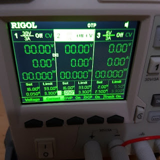
The power supply used in this example was the Rigol DP-832. This unit can provide 3 separate power sources.To supply the ±12V the power supply had to be setup to a specific configuration. Firstly channels 1 & 2 were used and tracking was enabled. This means that the channels follow each-other in respect to voltage and current. Each channel was set to 12V.
As can be seen in the pictures below;
+12V was from Channel 1 Positive terminal
Channel 1 negative was joined to the positive terminal of channel 2
These 2 terminals are the circuit’s ground
-12V was from Channel 2 Negative terminal
If you just have batteries to work with, a simple example of this can be shown using 2 x 9V batteries setup as shown below.


Comments
Post a Comment